Hack A Capello Alarm Clock To Auto-Dim at Night
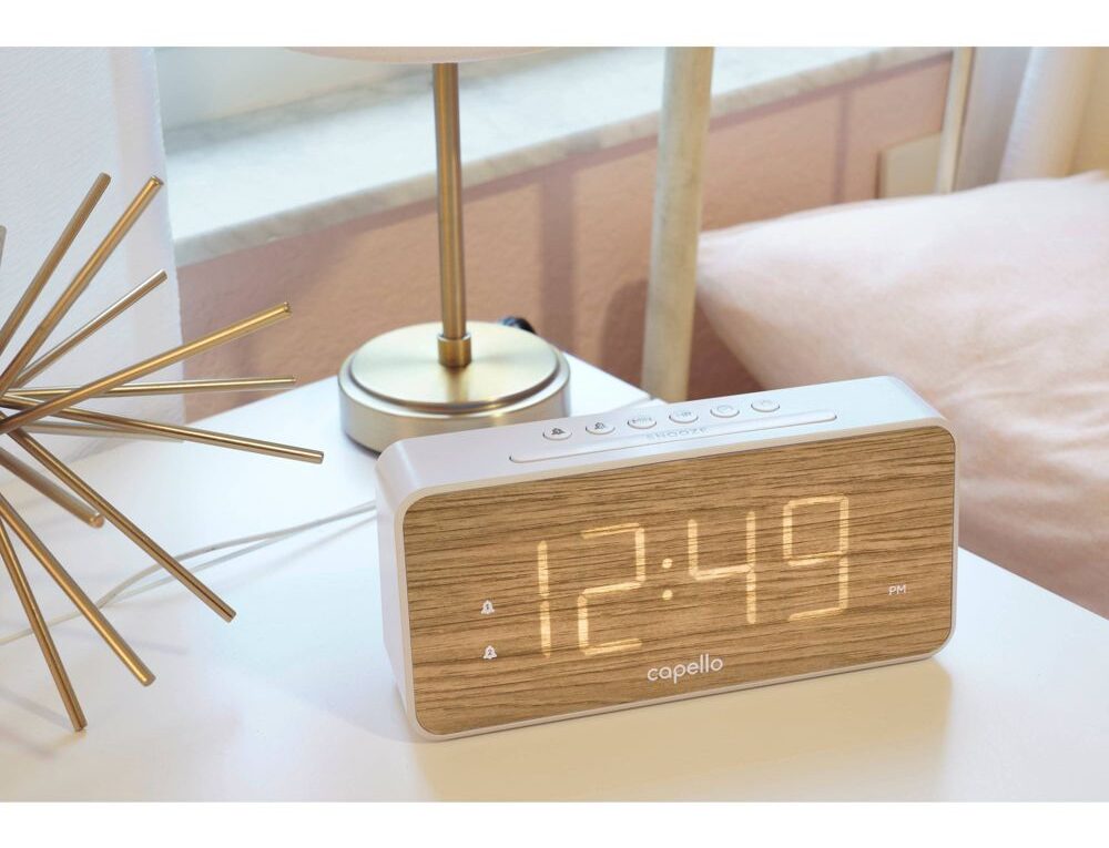
The Capello Big Time alarm clock is an attractive, inexpensive bedside clock commonly available at Target stores and online. It features a 3 1/2 digit numerical display using white LEDs that glow through a woodgrain effect front panel. The clock has three different brightness levels, selected by pressing a button on the top. However, even the dimmest setting is quite bright at night in a dark room, and if you are sensitive to light at night, the issue is worse because the light is white, not a muted red or green. This project will make the Capello clock automatically dim at night.
How the clock works
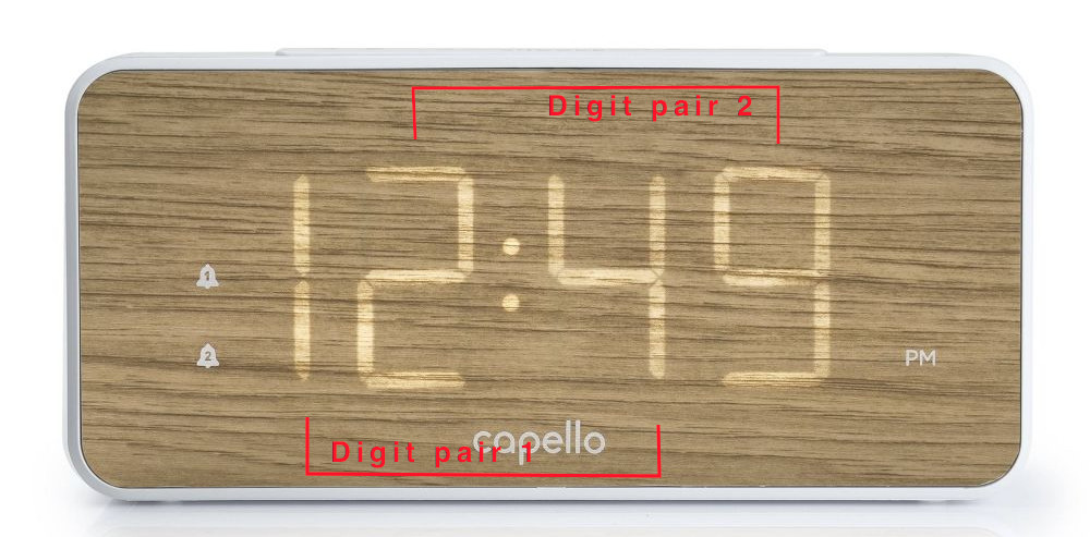
The clock has very few internal components – a single microcontroller and a few transistors and capacitors to drive the display using signals from the microcontroller. The display operates as two pairs of digits, whereby one pair is on while the other pair is off and they are switched on and off fast enough that the user does not perceive any flicker because of the LED’s residual glow and the user’s persistence of vision.
Each pair is driven by a transistor controlled using a pulse width modulated (PWM) signal of the same frequency (approx. 11Hz) and pulse width, but shifted by half a cycle. The digits are turned on when the signal from the microcontroller is low, and off when high.
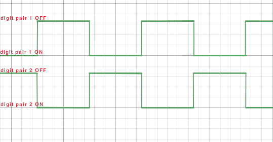
At the bright setting the PWM duty cycle is 50% (ie an on time of approx 44ms), at the medium setting the on time is 1.4ms and at the dim setting the on time is approx. 550µs.
Solution
We will disconnect the clock’s signal lines from the transistors that drive the display segments and modify the signal to reduce the “on” time as ambient light in the room decreases. We will monitor the light level using a photoresistor or (light dependent resistor, LDR) connected to an Atmel ATTiny85 microcontroller and generate signals that decrease the amount of time the display is turned on when ambient light levels decrease.
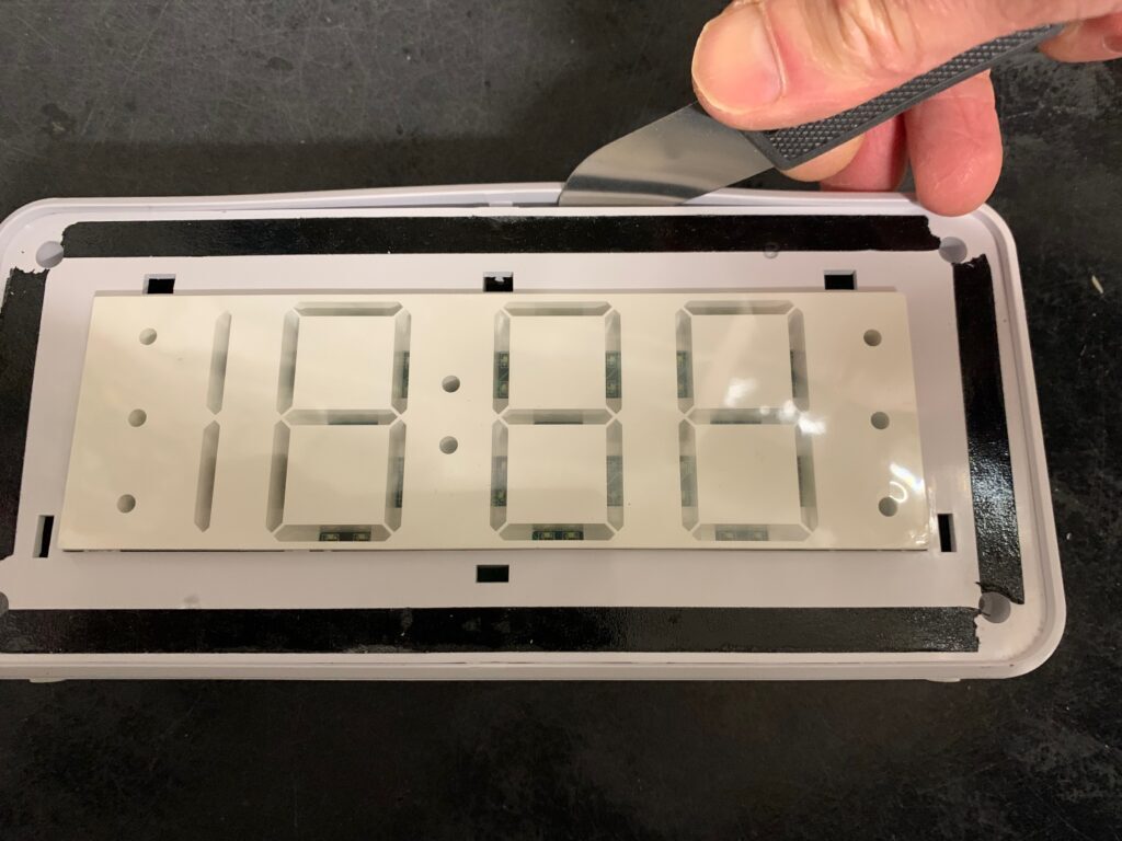
Disassembling the clock
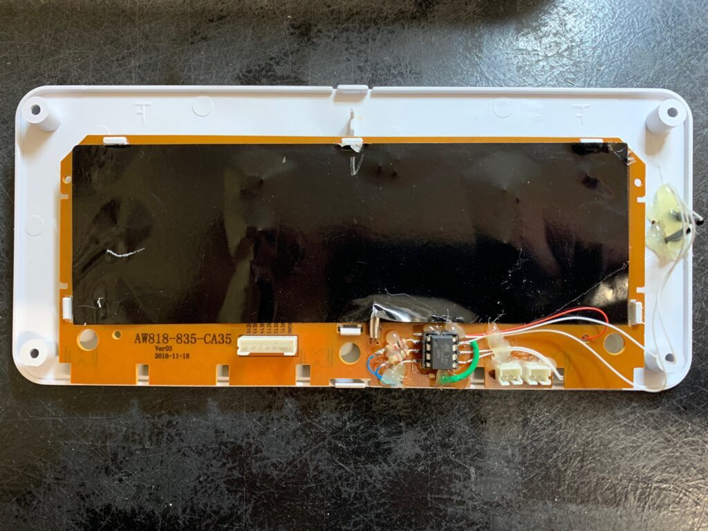
The front panel of the clock is about 2mm thick and held on with double sided tape. Use a pry tool or knife to carefully remove it.

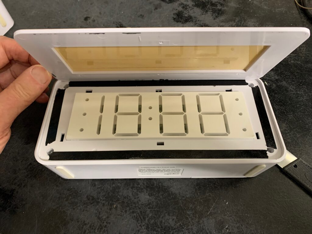
Remove the four screws in each corner of the display and then carefully pry it out from the case of the clock:
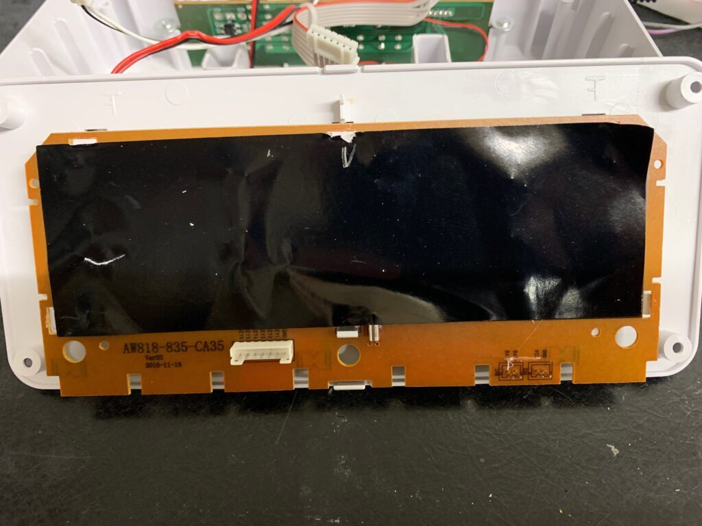
Carefully pry the 5 clips that attach the plastic frame to the circuit board to remove it.
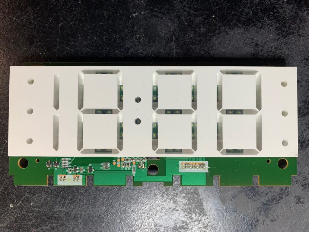
R6 and R7 connect the signals from the clock’s microcontroller (hidden under the display) to the two transistors Q1 and Q2 that drive the display.
Circuit
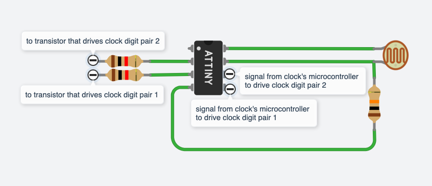
Pin 2 is PB1 and will be the output connected to the clock’s drive transistor Q2 for digit pair 2. Pin 3 is PB0 and will be the output connected to the clock’s drive transistor Q1 for digit pair 1. Pin 4 of the ATTiny will be connected to the clock’s ground. Pin 5 is PB4 and will be connected to the the clock’s resistor R6. Pin 6 is PB3 and will be connected to the clock’s resistor R7. Pin7 is analog input AD1 and will be connected to the LDR. Pin 8 will be connected to the clock’s Vcc which is 3.3v.
Modifications to the Clock
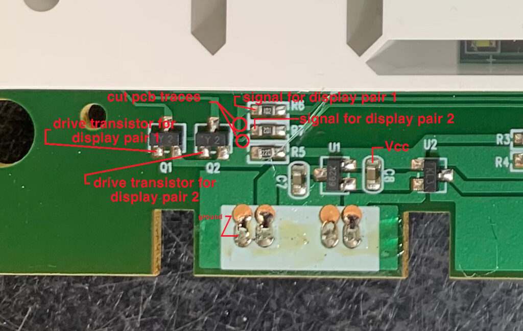
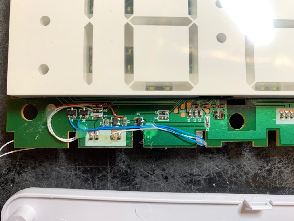
The traces on the clock are cut at the places marked in the picture to disconnect the clock’s display signal at R6 and R7 from the drive transistors Q1 and Q2.
Mount the ATTiny in a socket which is hot glued to the back of the display, along with the resistors. Drill a hole in the display frame and hot glue the LDR into the hole. Drill the fascia panel from the underside at the spot the LDR touches it, until there is just the thickness of the wood effect vinyl covering the hole. This allows light to reach the LDR through the front of the display without making a hole through the outside of the clock.
Program
Use the Arduino IDE to program the ATTiny using the following code:
/***
Hack to make the cheap Capello alarm clock auto dim at night
------------------------------------------------------------

Background
----------
The Capello Clock is a cheap alarm clock with a wood grain fascia covering a display composed of small white LEDs
arranged as 7 segment digits. The display glows through fascia to display the time without the LED's being directly
visible.
The clock has 3 brightness levels to allow the display brightness to be adjusted to the user's preference, but the
brightness does not auto adjust with ambient light conditions. This means that although during the day the display does
not seem very bright, it can be unpleasantly bright in a pitch dark room at night.

The clock's uC drives the display as two pairs of digits using a separate 3.3v 110Hz PWM signal for each,
shifted by a complete period so only one pair is powered at a time.
When the PWM signal is low that particular pair is powered.
There are three settings on the clock itself that set the display brightness by altering the pulse width
driving the display:
- brightest: signal pulse is approx 4.4ms
- medium: signal pulse is approx 1.4ms
- darkest: signal pulse is approx 0.55ms
Perceived brightness is approximately the square root of measured brightness.
Assuming that the display intensity is proportional to the pulse width, each subsequent brightness setting is approx 1/3
of the previous - square root of 0.33 is approx 0.5, so the perceived reduction in brightness is half.

Objective
---------
We want each pair of display digits to be turned on as normal, for the full length of the PWM pulse from the clock's uC
during daylight conditions, but reduced during darkness to lower the light level at night.
So we will turn the pair on at the beginning of the clocks's signal pulse and turn them off after a
duration of time that will decrease as ambient light levels decrease.
Ambient light is measured using an LDR connected to an analog input and connected such that high values
measured by the ADC correspond to high ambient light, low values with darkness.
*/

#define DISPLAY1_PIN PB0  // signal from clock's uC indicating display pair 1 should be turned on
#define DISPLAY2_PIN PB1  // signal from clock's uC indicating display pair 2 should be turned on
#define DRIVE1_PIN PB4    // output to transistor to power display pair 1
#define DRIVE2_PIN PB3    // output to transistor to power display pair 2
#if defined(ARDUINO_attiny)
  #define LDR_PIN 1       // ADC1 on the ATTiny is pin number 1
#else
  #define LDR_PIN ADC1D   // ADC1
#endif
#define TIMERCLOCK 200000
#define BRIGHTPULSE (0.0044 * TIMERCLOCK)  // number of timer clock cycles for bright setting 880
#define MEDIUMPULSE (0.0014 * TIMERCLOCK)  // number of timer clock cycles for medium setting 280
#define DIMPULSE (0.00055 * TIMERCLOCK)    // number of timer clock cycles for dim setting 110

// global variables declared volatile if they can change in interrupt handlers:
volatile uint16_t uiSignalTimer;       // measure the display signal pulse so we can adapt the drive pulse to brightness setting on the clock
volatile uint16_t uiSignalPulseWidth;  // holds how many timer cycles make a display signal pulse from the clock's uC
volatile uint16_t uiPulseWidth;        // holds the calculated number of timer cycle to create the pulse width for driving the display
volatile uint16_t uiPulseTimer;        // counts the timer cycles during an output drive pulse
uint16_t uiLDRval;                     // voltage on LDR: higher is darker (max is 1024 when pin voltage=supply voltage). LDR resistance approx .5k (bright light) to 1M+ (dark)
uint8_t uiPortMask = (1 << DRIVE1_PIN) | (1 << DRIVE2_PIN); // port mask for our output pins


void setup(){
  uiSignalPulseWidth = BRIGHTPULSE;   // start with bright setting pulse, it will update once we measure actual pulse length
  uiPulseWidth = uiSignalPulseWidth;  // set initial drive pulse width to match signal pulse width
  uiPulseTimer = 0;                   // initialize drive pulse timer
  uiLDRval = 1024;                    // start with ADC max value ie brightest possible ambient light

  DDRB = uiPortMask;  // setup display driver pins as outputs, everything else as input
  PORTB = uiPortMask; // set drive pins high ie LED off

  cli(); // disable interrupts

  #if defined(ARDUINO_attiny)
    // ATTiny configuration (data sheet: https://ww1.microchip.com/downloads/en/DeviceDoc/Atmel-2586-AVR-8-bit-Microcontroller-ATtiny25-ATtiny45-ATtiny85_Datasheet.pdf)

    // setup timer compare interrupt:
    TCCR0A = 0;              // set entire timer control register TCCR0A to 0
    TCCR0B = 0;              // same for TCCR0B
    TCNT0 = 0;               // initialize timer counter value to 0
    TCCR0B |= (1 << CS01);   // set CS01 bit to prescale the timer clock by 8 ie timer clock = system clock / 8 (note system clock is 16MHz)
    OCR0A = 9;               // set compare match register to a value that generates an interrupt at 200khz: (16MHz) / (200kHz*8) - 1 = 9 (must be <256. 8 is the prescale value above)
    TCCR0A |= (1 << WGM01);  // turn on CTC mode so we can do a compare match, ie timer interrupt flag set when it matches value in compare match register OCR0A
    TIMSK |= (1 << OCIE0A);  // enable timer compare interrupt, ie timer interrupt handler will get called

    // setup display signal pins to generate an interrupt on change:
    PCMSK = (1 << DISPLAY1_PIN) | (1 << DISPLAY2_PIN);    // enable PCINT handler (ISR) for display signal pins
    GIMSK |= (1 << PCIE);                                 // enable PCINT interrupt in the general interrupt mask
  #else
    // configuration for Arduino Uno, etc
    // (Atmel 328p datasheet: https://ww1.microchip.com/downloads/en/DeviceDoc/Atmel-7810-Automotive-Microcontrollers-ATmega328P_Datasheet.pdf)

    // setup timer compare interrupt:
    TCCR0A = 0;               // set entire timer control register TCCR0A to 0
    TCCR0B = 0;               // same for TCCR0B
    TCNT0 = 0;                // initialize timer counter value to 0
    TCCR0B |= (1 << CS01);    // set CS01 bit to prescale the timer clock by 8 ie timer clock = system clock / 8 (note system clock is 16MHz) = 2MHz
    OCR0A = 9;                // set compare match register to a value that generates an interrupt at 200khz: (16MHz) / (200kHz*8) - 1 = 9 (must be <256. 8 is the prescale value above)
    TCCR0A |= (1 << WGM01);   // turn on CTC mode so we can do a compare match, ie timer interrupt flag set when it matches value in compare match register OCR0A
    TIMSK0 |= (1 << OCIE0A);  // enable timer compare interrupt, ie timer interrupt handler will get called

    // setup display signal pins to generate an interrupt on change:
    PCMSK0 = (1 << DISPLAY1_PIN) | (1 << DISPLAY2_PIN);  // enable PCINT handler (ISR) for display signal pins
    PCMSK1 = 0;                                          // ensure other pins do not generate interrupts
    PCMSK2 = 0;                                          // ensure other pins do not generate interrupts
    PCICR |= (1 << PCIE0);                               // enable PCINT interrupt in the general interrupt mask
  #endif

  sei(); // enable interrupts
}


/**
  Timer compare match interrupt handler:
  - this will be called every time TIMERCLOCK counts the number in the compare match register set above,
  ie every 10/2,000,000 seconds, allowing us to measure/generate a pulse with a resolution of approx 5 us
*/
ISR(TIMER0_COMPA_vect){
  uiSignalTimer++;

  if (uiPulseTimer > 0) {
    uiPulseTimer--;
    // if pulse timer has reached zero then end the drive pulse (by setting output pins high)
    if (uiPulseTimer == 0) {
      PORTB |= uiPortMask;
    }
  }
}


/**
  PCINT (pin change interrupt) handler
  - called for state change (high or low) on ANY pin that we setup to trigger a PCINT (ie B0 and B1).
*/
ISR(PCINT0_vect) {
  uint8_t uiPortVal;

  // check if a signal pin went low
  uiPortVal = PINB | uiPortMask;
  if (~PINB & (1 << DISPLAY1_PIN)) {
    // Display1_PIN went low, we want to drive display pair 1 low to turn on
    uiPortVal ^= (1 << DRIVE1_PIN);
    // set up drive pulse timer
    uiPulseTimer = uiPulseWidth;
    // start measuring the signal pulse
    uiSignalTimer = 0;
  } else if (~PINB & (1 << DISPLAY2_PIN)) {
    // Display2_PIN went low, we want to drive display pair 2 low to turn on
    uiPortVal ^= (1 << DRIVE2_PIN);
    // set up drive pulse timer
    uiPulseTimer = uiPulseWidth;
    // start measuring the signal pulse
    uiSignalTimer = 0;
  } else {
    // both display signal pins high ie display off
    uiPulseTimer = 0;
    // start measuring the signal pulse
    uiSignalPulseWidth = uiSignalTimer;
  }
  // change the drive pins to the new state
  PORTB = uiPortVal;

  // reset the timer because there is a signal pin change
  TCNT0 = 0; // reset the timer count
  #if defined(ARDUINO_attiny)
    TIFR = (1 << OCF0A);    // make sure timer flag is clear
  #else
    TIFR0 = (1 << OCF0A);   // make sure timer flag is clear
  #endif
}


/**
  Main loop
  - do non time critical things here like measure the ambient light level, calculate the drive pulse length
*/
void loop(){
  // figure out which brightness setting the clock is set to and set the signal pulse width timer cycle count
  // we don't use the measured value directly because it fluctuates and causes flickering
  // when divided down and coupled with the variability of the LDR value
  if (uiSignalPulseWidth > 1.5 * MEDIUMPULSE) {
    // on brightest clock setting
    uiSignalPulseWidth = BRIGHTPULSE;
  }
  else if (uiSignalPulseWidth > 1.5 * DIMPULSE) {
    // on medium brightness clock setting
    uiSignalPulseWidth = MEDIUMPULSE;
  }
  else {
    // on lowest brightness clock setting
    uiSignalPulseWidth = DIMPULSE;
  }

  // read the LDR and average
  uiLDRval = (uiLDRval * 9 + analogRead(1)) / 10;
  // Make pulse width a fraction of signal pulse width based on light level based on measuring LDR resistance after installation:
  // ADC has max value 0f 1024 when input = supply voltage
  // with moderate ambient light at the lowest level we want before dimming starts, the LDR measures approx 30kohm,
  // so high value for uiLDRval is 1024 * 10k/(10k+30k) ~ 256
  // With no ambient light the LDR measures approx 1Mohm+
  // therefore ADC value should be 1024 * 10k/(10k+LDR)
  // therefore min possible value for uiLDRval should be 1024 * 10k/(10k+1000k) ~ 10

  // make sure minium pulse width is 1 (note DIMPULSE is less than 256)
  if (uiLDRval <= 256/DIMPULSE)
    uiLDRval = 1 + 256/DIMPULSE;
  uiPulseWidth = (uint32_t)uiSignalPulseWidth * uiLDRval / 256;
}
Configure an Arduino Uno or similar to act as an “Arduino ISP” programmer and then configure the Arduino IDE for ATTiny. The ATTiny also needs to be set to operate at 16MHz for this sketch, so set the clock speed to 16MHz and select “Upload boot loader” to set the ATTiny’s clock speed. After that, compile the sketch, and then upload it to the ATTiny by selecting “Upload Sketch” from the Tools menu in the IDE.
Reassemble and Test
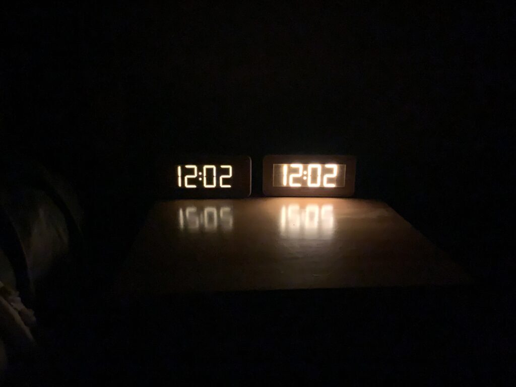
In daylight, the clock brightness should be unchanged. As the room darkens (or if you cover the part of the display where the LDR is located) the display should dim.