Raspberry Pi Media Player – Part 1, Hardware
This project shows you how to easily make a media player that can be used for storing and playing movies as well as streaming certain online content.
Materials
- RaspberryPi (preferably version 3)
- Micro SD card (8Gb or larger)
- 5v 2.5A Power Supply
- Case
- DC panel mount power connector (needs to match power supply cable)
- Male to female screw panel ethernet extension cable
- 2.54mm / 0.1″ female to female jumper cables
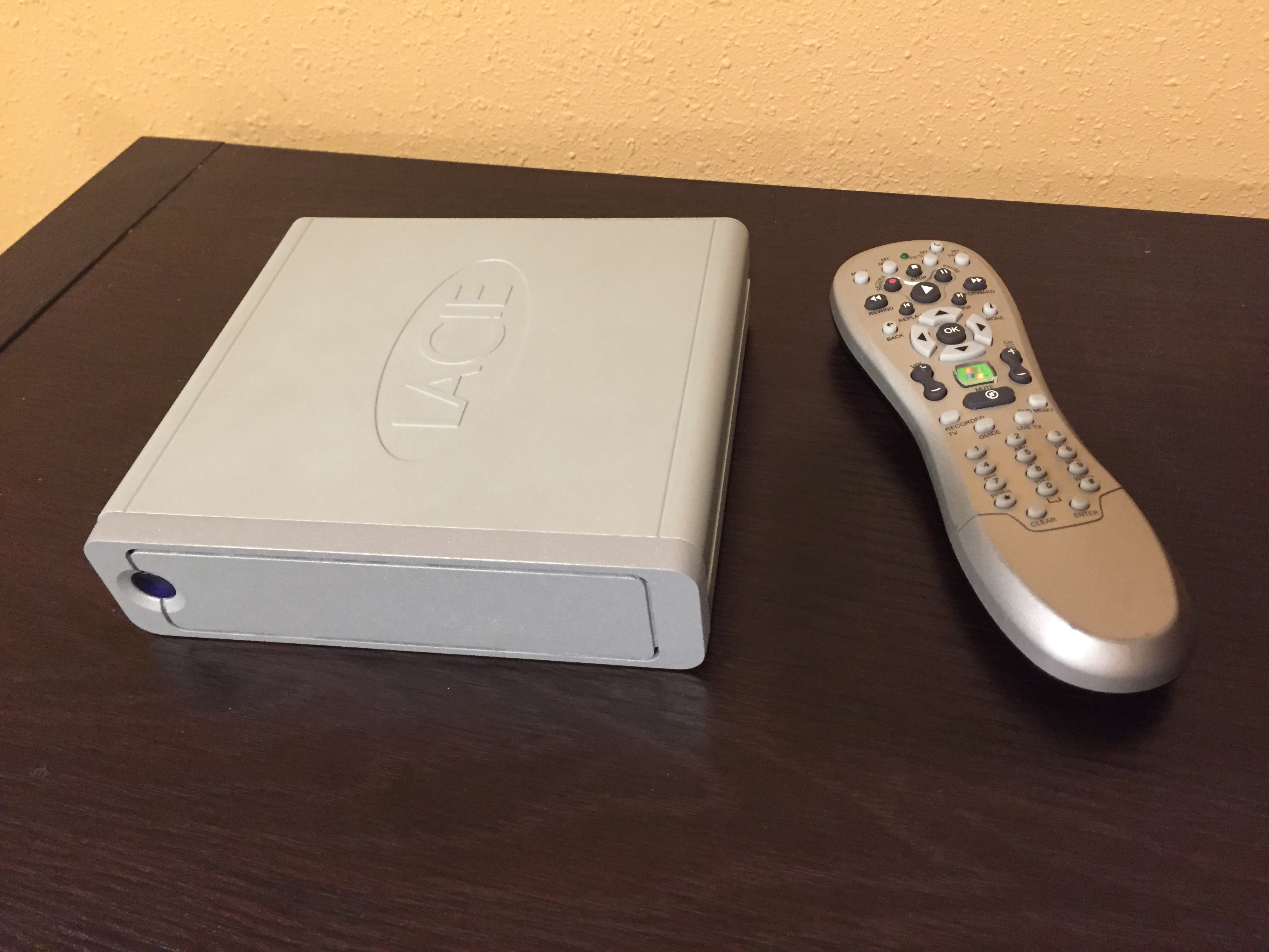
- IR remote control such as the Windows Media Center remote
- InfraRed Receiver (as a component or as USB dongle)
- USB Hard drive for storing media (optional but recommended)
- 1/8″ heat shrink sleeving
- Double sided foam sticky tape
- Superglue
Tools
- Screw drivers
- Soldering iron and solder
Procedure
Case Preparation
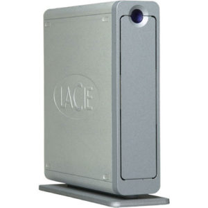
For my case I wanted something robust and fairly portable so that we could take movies with us for downtime when on vacation with the kids. I found an old LaCie external Firewire hard drive enclosure that I had lying around which originally held a 3.5″ desktop style hard drive. The case is composed of a combination of extruded, cast aluminum and steel and is very solid and well made, as well as having a reasonable amount of space inside to stuff everything in. You can still find these or something similar at a second hand shops or on eBay for not much money.
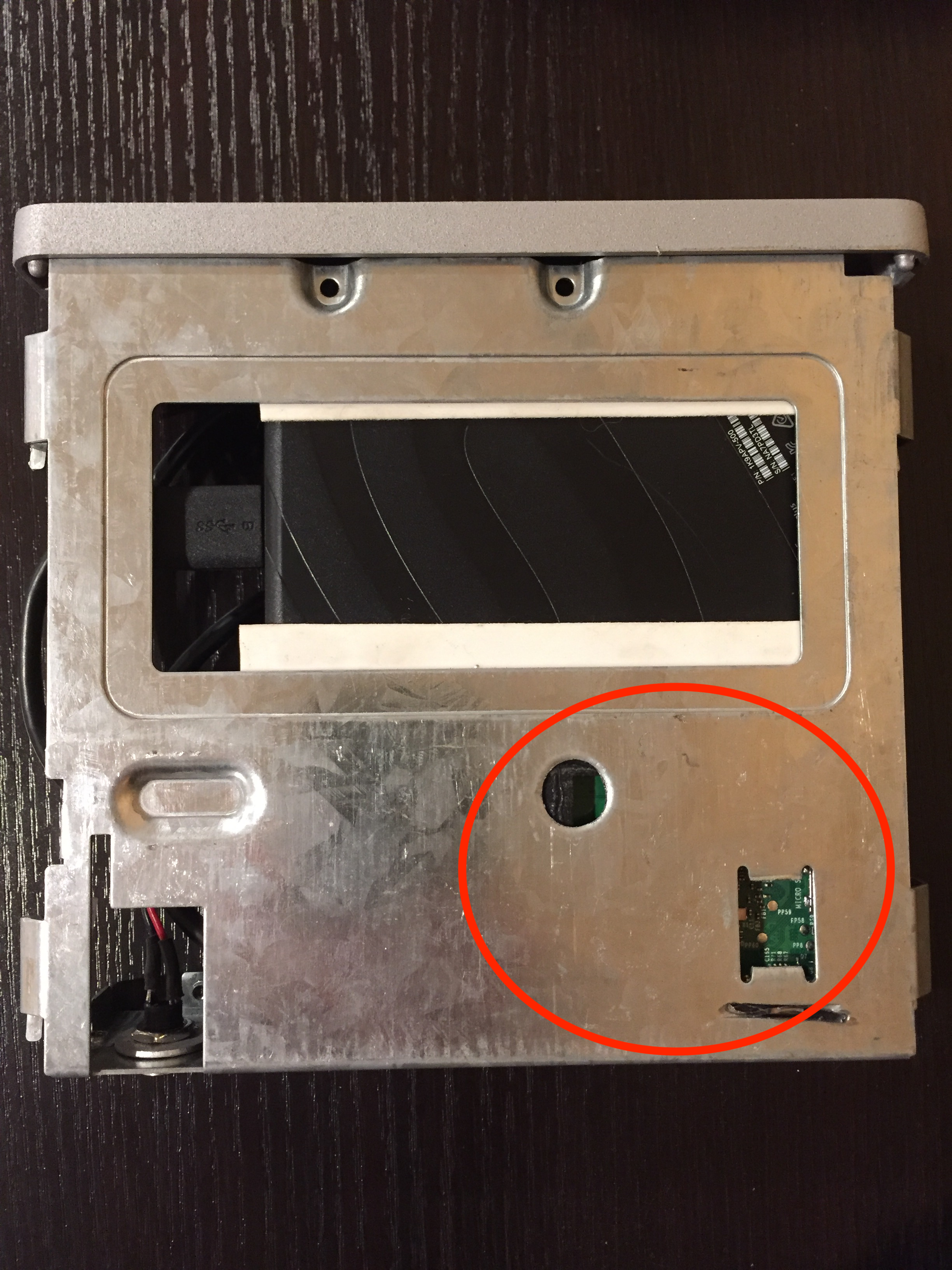
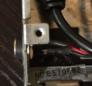
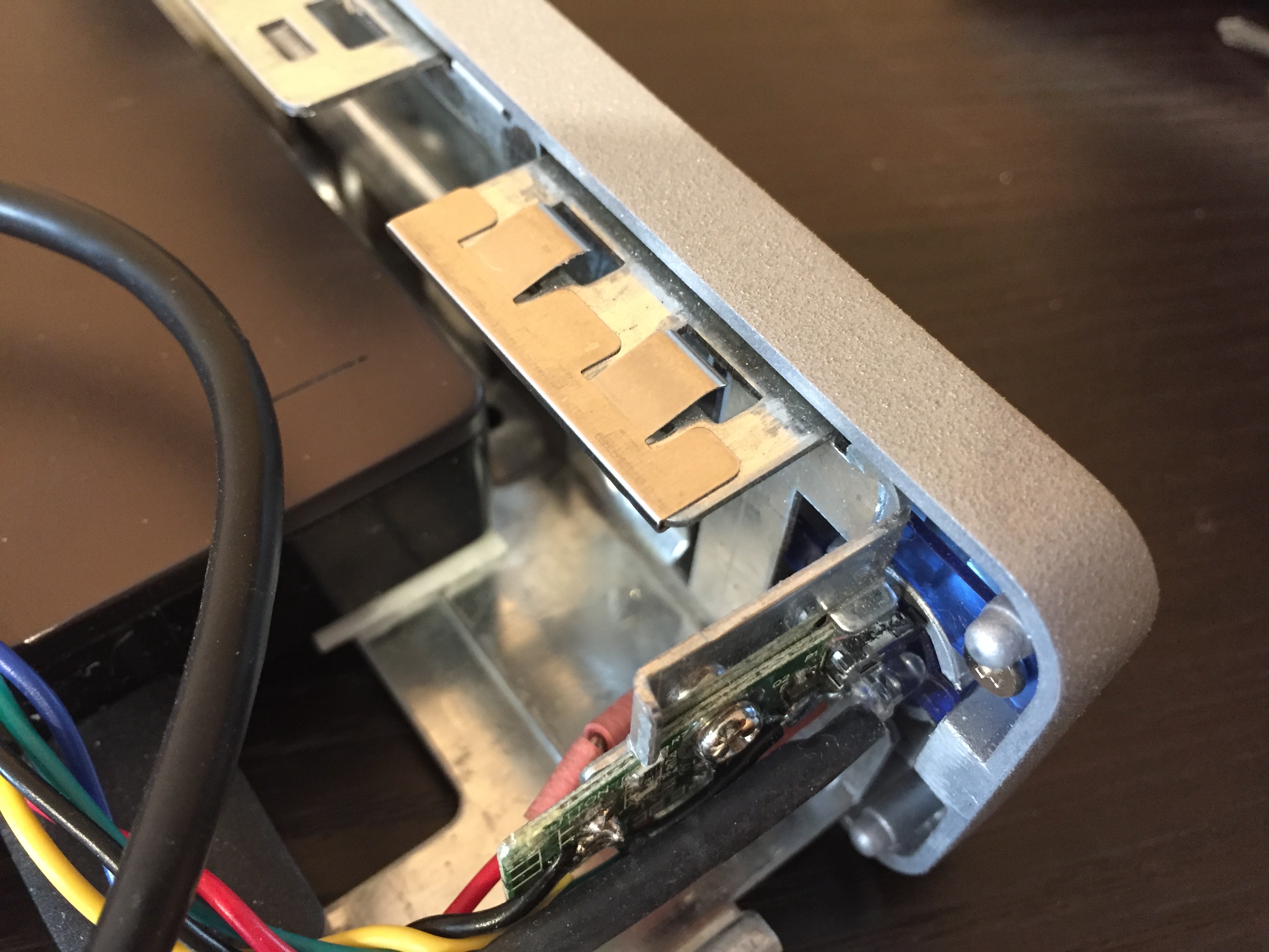
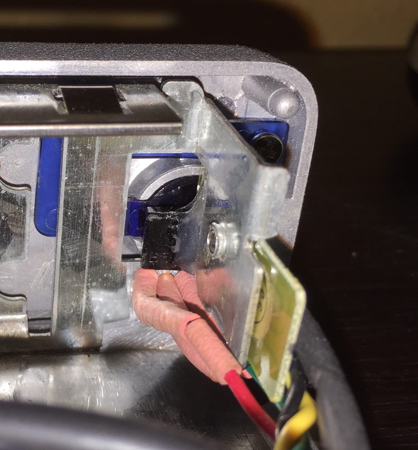
Unfortunately I did not take step by step pictures of the case modifications, but first the case was disassembled by undoing the two screws on the back. The backplate then comes off and the inside of the case slides out the front. Inside there were two boards – a controller board that provided the external connectors and interface to the hard drive, as well as a small board mounted behind the front panel containing the on off switch and power light. Both boards were removed and any mounting brackets that were not needed were cut away. The base of the case had raised “bumps” on which the hard drive was mounted – these were drilled out and filed flat (circled in red).
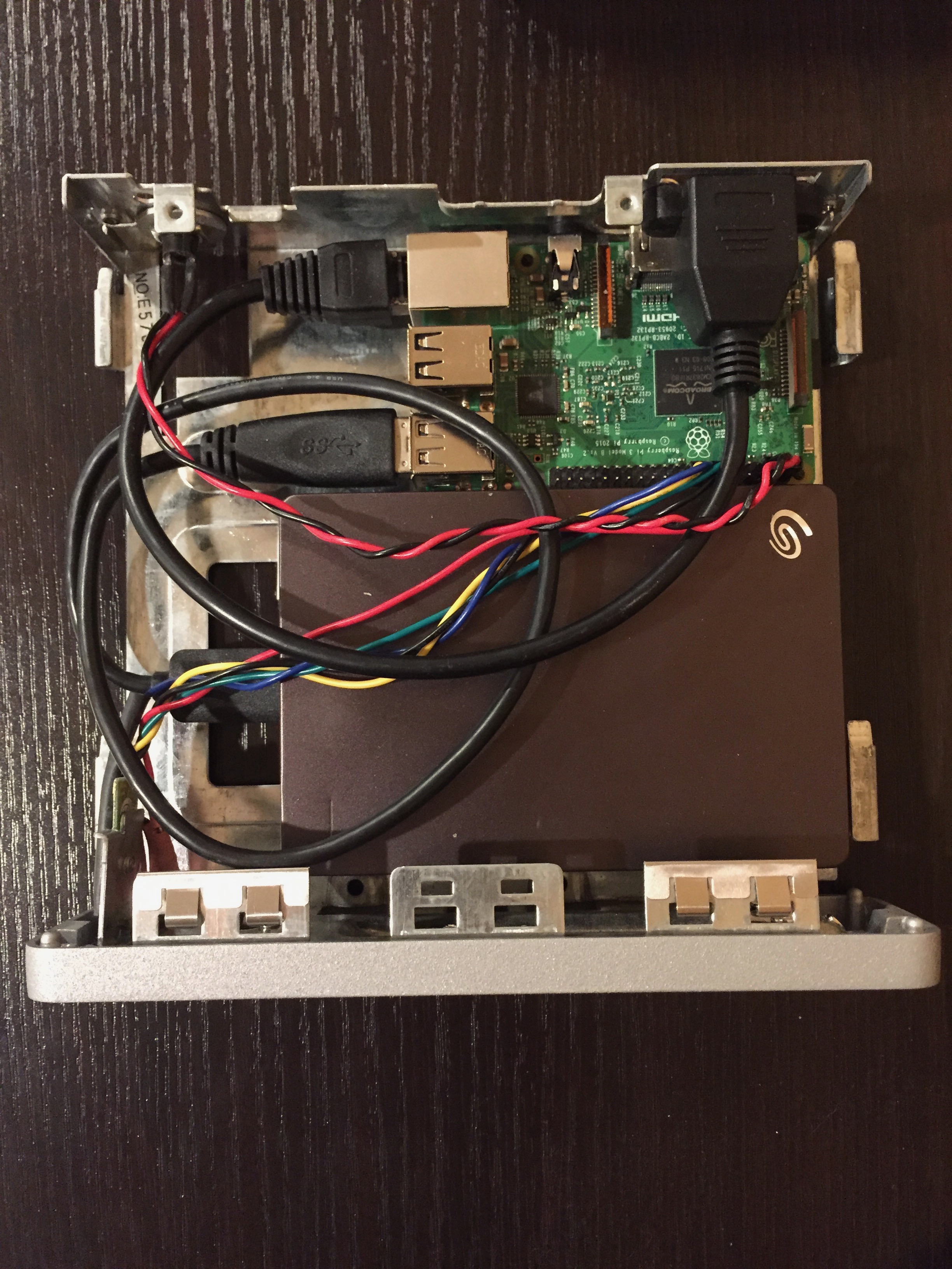
Once everything that would get in the way of mounting the Pi and hard drive had been removed, the PI and hard drive were placed in the case to decide how best to position them. At this point you will need to decide how to mount the Pi to the case – I made a 3D printed base plate like this one on Thingiverse then used double sided foam tape to hold it to the case, but using metal or nylon standoffs works well or you can save the complication of trying to drill holes in the case to line up with the mounting holes on the Pi by using self adhesive nylon standoffs, which you can find on Amazon, eBay, AliExpress, etc. The mounting holes on the Pi are a little smaller than 3mm or 7/64 inch, but if you file or drill them out to 3mm or 1/8 inch then you should be able to use 3mm self adhesive standoffs.
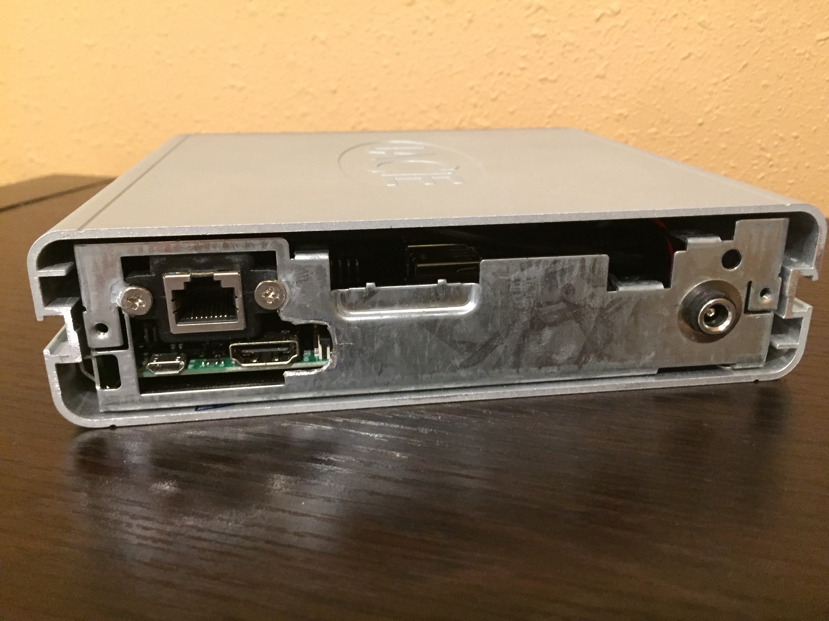
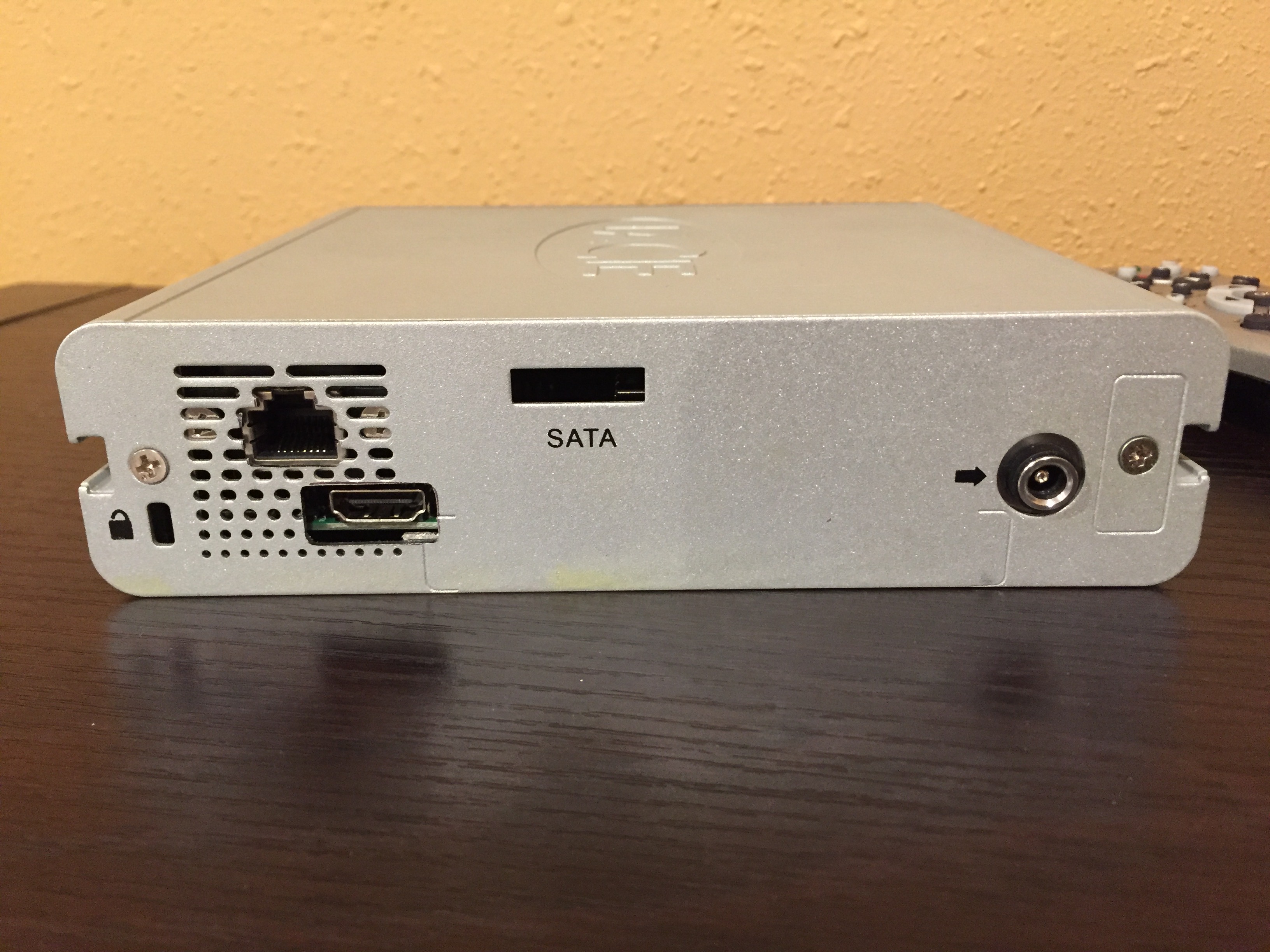
Once I was happy with the location of the Pi I marked the back cover of the case where the Pi’s HDMI and ethernet panel mount connectors lined up and cut out holes for them by drilling out most of the metal then filing the holes to shape.
Mounting the Components
The DC power connector was mounted to the case. Unfortunately the existing hole for the old power connector was slightly bigger than the new connector, so I used two thin washers either side of the hole in the case then tightened the lock nut on the connector.

Next the Pi and USB drive were mounted to the case using double sided foam sticky tape. The foam allows for some unevenness between the USB drive and the case as well as (hopefully) dampening any sound vibrations that the drive will make when spinning.
Connecting Everything Up
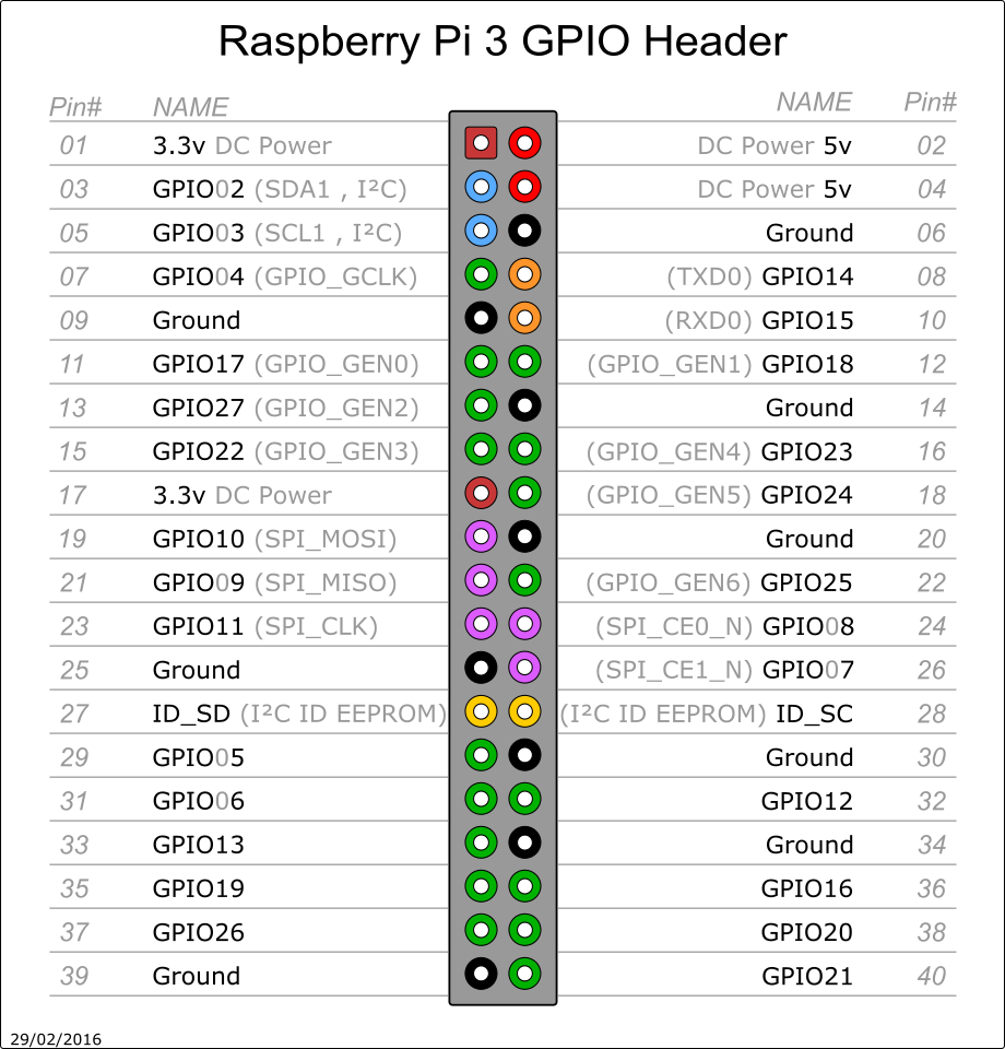
Two of the female to female jumpers were cut to reach from the barrel connector to pins #2 (5v) and #6 (ground) on the Pi. Heat shrink sleeving was put over the cut ends then the 5v jumper was soldered to the center contact of the barrel connector (since my power adapter is center connector positive) and the ground jumper to the outside contact of the barrel connector. The heat shrink sleeving was then slid over the solder joints.
Power Button
The case originally had a transparent plastic power button on the front with a PCB mounted just behind the button containing an LED and a switch. Unfortunately the LED requires more than 3.3v (the output of the Pi’s GPIO pins) to drive it, but the switch was reused by taking two of the female to female jumpers and cutting the connector off one end and soldering one to the ground connection of the PCB and one to the connection that lead to the button. The ground jumper was plugged into pin #14 of the Pi’s GPIO header and the jumper connected to the switch was plugged into pin #18.
Power LED
 The only LED I had on hand that would work with 3.3v was a red one. The cathode of the LED was soldered to a ground contact on the board with the LED positioned so that it faced the inside of the power button. Another female jumper was snipped, covered with heat shrink then soldered to a 330 Ohm resistor, the other end of the resistor was soldered to the anode of the LED and the heat shrink sleeving slid over the resistor and LED leg to prevent any shorting. Some hot glue to secure the heat shrink covered resistor to the PCB would be a good idea. The other end of the jumper was plugged into pin #16 of the Pi’s GPIO header.
Infra Red Receiver
There are several different protocols for infra red remotes and it is important to get a receiver that will work with the remote control you are going to use. The Windows Media remote I used makes use of the RC6 infra red protocol which uses a 38kHz carrier signal. I therefore had to use a receiver that works with RC6/38kHz – I removed one from the front panel of a defunct Windows Media PC, but receivers such as this one from Sparkfun should work.
A female jumper was cut, sleeving placed over the cut end and a 47 Ohm resistor soldered to the cut end. The other end of the resistor was soldered to the supply pin of the receiver (typically pin 3) and the sleeving slid over the resistor and solder connections. The other end of the jumper was plugged into pin 4 (5v) of the Pi’s GPIO connector.
A short piece of wire was soldered to the ground pin of the receiver (typically pin 2), the soldered connection was covered with sleeving and the other end of the wire soldered to the ground connection of the power button PCB.
 Another female jumper was snipped, sleeved and soldered to the out put of the receiver and the sleeving slid over the solder joint. The jumper was plugged into pin 12 of the Pi’s GPIO connector.
Lastly the receiver was glued to the power button PCB so that it faced the inside of the button.
USB Drive
The USB drive was plugged into a USB port on the Pi.
Ethernet Cable
The panel mount ethernet cable was fastened to the back of the case and plugged into the Pi.
Next: Part 2 – Install Software and Finish